
26 Dec 2025
107 Compressor Parts
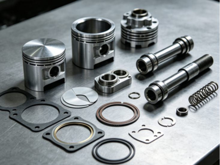
Core Purpose & Application Overview
This classified spare parts list is exclusively compatible with 107 Series Air Compressors (including models matching part number prefixes 107.11, 107.06, 107.130, etc.). It is tailored to meet the refined needs of target users such as industrial maintenance teams, factory equipment managers, and authorized service providers—specifically addressing pain points like unplanned downtime due to spare part shortages, mismatched components leading to secondary equipment damage, and lack of professional guidance on part maintenance. The core purpose of these spare parts is to ensure the continuous, efficient, and safe operation of 107 Series Air Compressors by providing original-standard replacement components, while offering detailed maintenance guidelines to extend part service life and reduce overall maintenance costs. These parts are widely applied in industrial production scenarios such as manufacturing plants, mining operations, and construction sites where 107 Series Air Compressors are critical for power transmission and pneumatic system operation.
1. Cylinder Liner Assemblies (Critical for Compression Chamber Sealing & Pressure Stability)
Cylinder liners are the key components forming the compression chamber of 107 Series Air Compressors. Their wear resistance directly determines the compressor's air displacement, pressure stability, and energy efficiency. A damaged liner can cause air leakage, reduced compression efficiency, and even scratch the piston, leading to costly repairs. This category includes chrome-plated liners of different diameters, designed for precise matching with corresponding piston assemblies to ensure optimal compression performance.
ITEM# | DESCRIPTION | Part No. | MATERIAL | Main Wear Reasons | Damage Prevention Notes |
1 | Φ 180 mm Liner (Chrome) | 107.11.110.31 | High-strength cast iron with hard chrome plating (HRC ≥ 60) | 1. Abrasion from impurities (dust, metal particles) in the intake air; 2. Long-term high-temperature and high-pressure operation leading to chrome layer peeling; 3. Improper lubrication causing dry friction between liner and piston. | 1. Regularly replace the air filter element to ensure intake air cleanliness; 2. Check and maintain the lubrication system regularly to ensure sufficient and clean lubricating oil; 3. Avoid overloading the compressor (operating beyond rated pressure/temperature) for extended periods. |
2 | Φ 170 mm Liner (Chrome) | 107.11.110.30 | High-strength cast iron with hard chrome plating (HRC ≥ 60) | 1. Erosion from moisture condensation in the cylinder (causing rust and pitting); 2. Abrasion due to misalignment between piston and liner; 3. Fatigue damage from frequent start-stop cycles. | 1. Regularly drain the condensate from the cylinder and air storage tank; 2. Conduct periodic alignment checks of the piston and liner assembly during maintenance; 3. Reduce unnecessary frequent start-stops; ensure the compressor's start-stop control system is functioning properly. |
3 | Φ 160 mm Liner (Chrome) | 107.11.110.29 | High-strength cast iron with hard chrome plating (HRC ≥ 60) | 1. Abrasion from contaminated lubricating oil (containing metal debris or sludge); 2. Thermal shock damage from sudden temperature changes during operation; 3. Wear caused by improper installation (scratches from installation tools). | 1. Replace lubricating oil and oil filter according to the recommended maintenance cycle; 2. Avoid sudden loading of the compressor when the machine is not preheated; 3. Use special installation tools and follow the correct installation procedure to prevent scratches on the liner inner wall. |
2. Piston Assemblies & Related Components (Key for Reciprocating Compression Motion)
Piston assemblies are the core moving parts of 107 Series Air Compressors, converting mechanical energy into gas pressure energy. Piston rubbers (sealing rings) are critical for ensuring the airtightness of the compression chamber, while piston rods and clamps ensure stable reciprocating motion. Damage to these components can result in reduced compression efficiency, air leakage, and abnormal machine vibration. This category covers piston assemblies, piston rubbers, piston rods, and piston rod clamps of different specifications, all designed for precise fit with 107 Series compressors.
ITEM# | DESCRIPTION | Part No. | MATERIAL | Main Wear Reasons | Damage Prevention Notes |
1 | Φ 180 mm Piston Complete | 107.11.130.00 | Aluminum alloy (piston body) + nitrile rubber (sealing rings) + steel (connecting pins) | 1. Wear of sealing rings due to long-term friction with the cylinder liner; 2. Fatigue damage of the piston body caused by repeated impact during reciprocation; 3. Corrosion from acidic condensate in the cylinder. | 1. Regularly inspect the wear condition of piston sealing rings and replace them in time; 2. Control the operating pressure within the rated range to reduce impact load on the piston; 3. Maintain proper air humidity and drainage to prevent condensate accumulation and corrosion. |
2 | Φ 180 mm Piston Rubber | 107.11.130.00 | High-temperature resistant nitrile rubber (NBR, temperature resistance up to 120℃) | 1. Aging and hardening due to long-term exposure to high temperatures; 2. Abrasion from friction with the cylinder liner (exacerbated by impurities); 3. Chemical erosion from incompatible lubricating oil or gas medium. | 1. Use lubricating oil that is compatible with NBR rubber; 2. Ensure the air filter is effective to prevent impurities from entering the compression chamber; 3. Avoid prolonged operation of the compressor at temperatures exceeding 120℃. |
3 | Φ 170 mm Piston Complete | 107.06.70.00 | Aluminum alloy (piston body) + nitrile rubber (sealing rings) + steel (connecting pins) | 1. Uneven wear caused by piston misalignment; 2. Fatigue cracking of the piston skirt due to excessive load; 3. Damage to sealing rings from sudden pressure surges. | 1. Periodically check and adjust the piston alignment; 2. Install a pressure relief valve to prevent pressure surges in the compression chamber; 3. Avoid overloading the compressor for long periods. |
4 | Φ 170 mm Piston Rubber | 107.06.70.00 | High-temperature resistant nitrile rubber (NBR, temperature resistance up to 120℃) | 1. Wear due to insufficient lubrication between the rubber and liner; 2. Aging caused by long-term contact with oxygen and high temperatures; 3. Scratches from sharp impurities in the air. | 1. Ensure the lubrication system is functioning properly to maintain a uniform oil film; 2. Store spare piston rubbers in a cool, dry, and oxygen-isolated environment; 3. Regularly clean the air intake pipeline to remove potential sharp impurities. |
5 | Φ 160 mm Piston Complete | 107.06.68.00 | Aluminum alloy (piston body) + nitrile rubber (sealing rings) + steel (connecting pins) | 1. Corrosion of the piston body from moisture in the compressed air; 2. Wear of the connecting pin hole due to repeated rotation; 3. Damage to sealing rings from thermal cycling (alternating heating and cooling). | 1. Install a dryer in the compressed air system to reduce moisture content; 2. Regularly inspect the connecting pin and pin hole for wear and replace if necessary; 3. Avoid frequent start-stop cycles that cause rapid thermal cycling. |
6 | Φ 160 mm Piston Rubber | 107.06.68.00 | High-temperature resistant nitrile rubber (NBR, temperature resistance up to 120℃) | 1. Compression set (permanent deformation) due to long-term continuous compression; 2. Abrasion from friction with the cylinder liner; 3. Damage from chemical contaminants in the intake air. | 1. Allow the compressor to run idle for a few minutes before shutting down to relieve pressure on the piston rubber; 2. Replace piston rubbers at regular intervals even if no obvious damage is found; 3. Install a pre-filter for the intake air if the working environment has high chemical contamination. |
7 | Piston Rod | 107.11.110.39 | High-carbon steel (45#) with chrome plating (surface roughness Ra ≤ 0.8 μm) | 1. Wear of the chrome layer due to friction with the seal; 2. Bending deformation caused by uneven lateral force; 3. Corrosion from moisture and chemical media. | 1. Regularly inspect the seal for wear to reduce friction on the piston rod; 2. Ensure the piston rod is properly aligned during installation and maintenance; 3. Apply anti-corrosion grease to the piston rod surface when the compressor is not in use for a long time. |
8 | Piston Rod Clamp | 107.11.114.00 | Alloy steel (40Cr) with quenching and tempering treatment (hardness HRC 35-40) | 1. Fatigue damage due to repeated vibration during operation; 2. Wear of the clamping surface due to loosening and sliding; 3. Deformation caused by over-tightening during installation. | 1. Regularly check the tightness of the clamp and re-tighten if necessary; 2. Ensure the clamping surface is clean and free of impurities before installation; 3. Use a torque wrench to tighten the clamp bolts according to the recommended torque value. |
3. Valve Assemblies & Related Components (Essential for Air Intake/Exhaust Control)
Valve assemblies (including valve seats, valve complete, valve springs, etc.) control the timing of air intake and exhaust in 107 Series Air Compressors. Their performance directly affects the compressor's air displacement, efficiency, and noise level. Malfunctioning valves can cause reverse airflow, reduced compression efficiency, and even damage to other components. This category includes all key valve-related components, designed to ensure precise opening and closing timing and reliable sealing performance.
ITEM# | DESCRIPTION | Part No. | MATERIAL | Main Wear Reasons | Damage Prevention Notes |
1 | Valve Seat | 107.11.140.04 | High-chromium cast iron (Cr15Mo3) with precision grinding | 1. Abrasion from repeated contact with the valve disc; 2. Corrosion from acidic condensate; 3. Pitting damage caused by pressure shocks. | 1. Regularly inspect the valve seat surface for wear and scratches; 2. Maintain proper drainage to prevent condensate accumulation; 3. Install a shock absorber in the air pipeline to reduce pressure shocks. |
2 | Valve Complete | 107.11.140.01 | Steel (valve disc) + nitrile rubber (sealing ring) + alloy steel (valve stem) | 1. Wear of the valve disc sealing surface; 2. Bending of the valve stem due to uneven force; 3. Aging of the sealing ring due to high temperatures. | 1. Replace the valve complete if the sealing surface is worn or pitted; 2. Ensure the valve stem moves freely without jamming; 3. Avoid prolonged operation at high temperatures to prevent sealing ring aging. |
3 | Valve Spring | - | Stainless steel (304) with heat treatment (fatigue life ≥ 10^6 cycles) | 1. Fatigue failure due to repeated compression and extension; 2. Corrosion from moisture and chemical media; 3. Deformation caused by overheating. | 1. Replace valve springs at regular intervals according to the maintenance cycle; 2. Keep the valve chamber dry and clean; 3. Monitor the compressor's operating temperature to avoid overheating. |
4 | Valve Guide Bushing | - | Copper alloy (CuSn10Pb10) with self-lubricating properties | 1. Wear due to friction with the valve stem; 2. Seizure caused by insufficient lubrication; 3. Corrosion from moisture. | 1. Ensure sufficient lubrication of the valve stem and guide bushing; 2. Regularly inspect the guide bushing for wear and replace if the clearance exceeds the limit; 3. Maintain proper drainage to prevent moisture from entering the valve chamber. |
5 | Valve Clip (Locking Clip) | 107.11.110.52-1 | Spring steel (65Mn) with surface galvanizing | 1. Fatigue failure due to repeated expansion and contraction; 2. Corrosion from moisture; 3. Damage caused by improper installation (over-stretching). | 1. Use special tools for installation to avoid over-stretching; 2. Regularly inspect the clip for deformation or corrosion; 3. Replace all valve clips when replacing the valve assembly to ensure uniform performance. |
6 | Valve Rubber (Insert) | 107.11.140.03 | Fluororubber (FKM, temperature resistance up to 200℃, chemical resistance) | 1. Aging and hardening due to high temperatures and chemical media; 2. Abrasion from repeated contact with the valve disc; 3. Compression set due to long-term continuous pressure. | 1. Use compatible lubricating oil and avoid contact with incompatible chemicals; 2. Regularly inspect the valve rubber for cracks or hardening; 3. Allow the compressor to cool down before shutting down to relieve pressure on the valve rubber. |
4. Sealing Components (Critical for Preventing Air & Oil Leakage)
Sealing components are essential for maintaining the airtightness and oil tightness of 107 Series Air Compressors. Leakage of air or lubricating oil can lead to reduced compression efficiency, increased energy consumption, and environmental pollution. This category includes various seals of different sizes, designed to fit specific positions such as cylinder liners, cylinder heads, valve covers, and intermediate rods, ensuring reliable sealing under high temperature and high pressure conditions.
ITEM# | DESCRIPTION | Part No. | MATERIAL | Main Wear Reasons | Damage Prevention Notes |
1 | Liner Seal (210 x 198 x 8.6) mm | - | High-temperature resistant silicone rubber (VMQ, temperature resistance up to 180℃) | 1. Aging and cracking due to high temperatures; 2. Abrasion from friction with the liner and cylinder block; 3. Damage caused by improper installation (scratches). | 1. Avoid prolonged operation of the compressor at temperatures exceeding 180℃; 2. Ensure the installation surface is clean and smooth; 3. Use a press tool for installation to avoid uneven force and scratches. |
2 | Cylinder Head Seal (270 x 189 x 9) mm | - | Nitrile rubber (NBR) with fabric reinforcement (temperature resistance up to 120℃) | 1. Compression set due to long-term high-pressure clamping; 2. Aging due to high temperatures; 3. Damage from chemical erosion of lubricating oil. | 1. Tighten the cylinder head bolts according to the recommended torque to avoid over-clamping; 2. Replace the seal at regular intervals even if no obvious damage is found; 3. Use lubricating oil compatible with NBR rubber. |
3 | Valve Cover Seal (190 x 172 x 9) mm | - | EPDM rubber (temperature resistance up to 150℃, weather resistance) | 1. Aging due to exposure to air and high temperatures; 2. Wear from vibration during operation; 3. Damage caused by over-tightening of the valve cover bolts. | 1. Keep the valve cover clean and free of debris; 2. Tighten the valve cover bolts evenly with a torque wrench; 3. Store spare seals in a sealed container to avoid exposure to air and sunlight. |
4 | Intermediate Rod Seal (140 x 109 x 14) mm | 107.11.97.00 | Polyurethane (PU) with high wear resistance (Shore hardness A 90) | 1. Abrasion from friction with the intermediate rod; 2. Damage from metal particles or impurities; 3. Aging due to high temperatures. | 1. Regularly inspect the intermediate rod surface for wear and scratches; 2. Ensure the sealing chamber is clean and free of impurities; 3. Monitor the operating temperature to avoid overheating. |
5 | Diaphragm | 107.130.01.00-1 | Reinforced fluororubber (FKM) with fabric layer (pressure resistance up to 1.6 MPa) | 1. Fatigue failure due to repeated deformation; 2. Chemical erosion from the medium; 3. Damage from excessive pressure. | 1. Control the operating pressure within the rated range; 2. Avoid contact with incompatible chemicals; 3. Replace the diaphragm at regular intervals according to the maintenance cycle. |
5. Fastening & Structural Components (Ensuring Stable Assembly & Operation)
Fastening and structural components such as locking plates, locking clips, cages, and stabilizers ensure the stable assembly and operation of 107 Series Air Compressors. Loosening or damage to these components can lead to abnormal vibration, component displacement, and even serious equipment failure. This category includes high-strength fastening and structural parts designed to withstand the vibration and load during compressor operation.
ITEM# | DESCRIPTION | Part No. | MATERIAL | Main Wear Reasons | Damage Prevention Notes |
1 | Locking Plate | 107.11.110.65-1 | Carbon steel (Q235) with surface painting | 1. Fatigue damage due to repeated vibration; 2. Corrosion from moisture and environmental factors; 3. Deformation caused by improper installation. | 1. Regularly check the locking plate for deformation or loosening; 2. Apply anti-corrosion paint to the surface if signs of corrosion are found; 3. Follow the correct installation procedure to avoid over-bending. |
2 | Locking Clip | 107.11.110.52 | Spring steel (65Mn) with surface galvanizing | 1. Fatigue failure due to repeated expansion and contraction; 2. Corrosion from moisture; 3. Damage caused by over-stretching during installation. | 1. Use special tools for installation to avoid over-stretching; 2. Regularly inspect the clip for deformation or corrosion; 3. Replace all locking clips when performing major maintenance. |
3 | Cage | 107.11.330.00 | Alloy steel (Q345) with welding and surface treatment | 1. Welding seam fatigue due to long-term vibration; 2. Corrosion from environmental factors; 3. Deformation caused by impact or excessive load. | 1. Regularly inspect the welding seams for cracks; 2. Keep the cage clean and free of debris; 3. Avoid impact on the cage during equipment transportation or maintenance. |
4 | Stabilizer | 107.130.02 | Cast iron (HT200) with precision machining | 1. Wear of the contact surface due to vibration; 2. Corrosion from moisture; 3. Cracking due to excessive load. | 1. Regularly inspect the contact surface for wear and replace if necessary; 2. Maintain a dry operating environment; 3. Ensure the stabilizer is properly installed to distribute the load evenly. |
Procurement Guidance
All the above spare parts are designed and manufactured in strict accordance with the original specifications of 107 Series Air Compressors, ensuring perfect compatibility and reliable performance. Choosing these genuine-standard spare parts can effectively reduce equipment failure rates, extend service life, and lower long-term maintenance costs. We recommend that you purchase spare parts based on your equipment's maintenance cycle and actual operating conditions to avoid unplanned downtime caused by part shortages. For any questions about part selection, installation, or maintenance, our professional technical team is ready to provide you with one-on-one consulting services. Whether you need a single part or a customized spare part package, we can meet your personalized needs. Please contact us to start your procurement process and enjoy the peace of mind brought by high-quality spare parts and professional technical support.
Technical Reference Standards
To help you better manage and maintain 107 Series Air Compressors, we provide the following technical reference standards:
• Spare Part Replacement Cycle Reference: Cylinder liners, piston assemblies, and valve assemblies are recommended to be inspected every 2000 operating hours and replaced every 8000-10000 operating hours; Sealing components (piston rubber, valve rubber, seals) are recommended to be replaced every 4000-6000 operating hours; Fastening components (locking plates, locking clips) should be inspected every 500 operating hours and replaced if any deformation or corrosion is found.
• Common Fault Diagnosis Guide: If the compressor has reduced air displacement, check the valve assembly and piston rubber for wear; If there is air leakage, inspect the sealing components and valve seat; If there is abnormal vibration, check the piston rod alignment and fastening components for looseness.
• Maintenance Operation Specifications: When replacing spare parts, ensure the equipment is shut down and the pressure is relieved; Use special tools for installation to avoid component damage; After replacement, conduct a test run to check the equipment's operating status before formal use.