
29 May 2026
30178348-600 VARCO Driven Pressure Hydraulic Control Valve & Counterbalance Cylinder Component Suite
1. Product Overview & Core Application Purpose
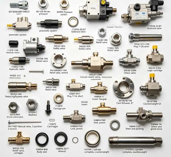
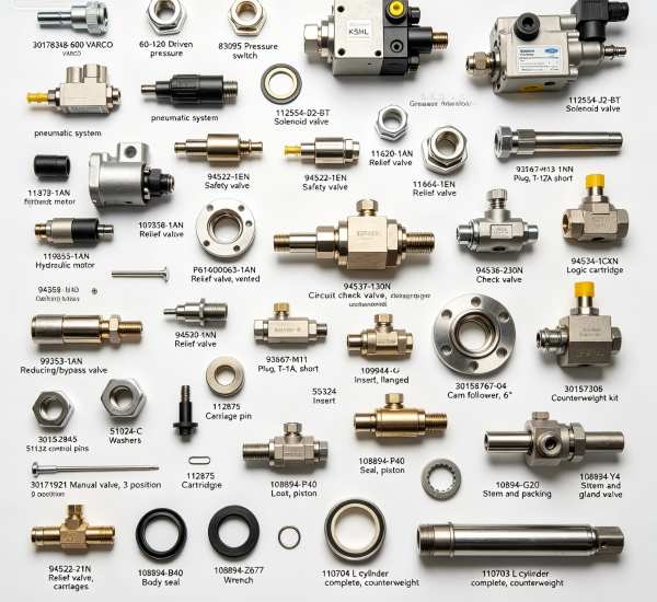
This comprehensive hydraulic component assembly centers on 30178348-600 VARCO driven pressure core components, multi-spec pressure switches, solenoid valves, relief valve cartridges, counterbalance cylinders and matched mechanical sealing kits, professionally engineered for VARCO series top drive hydraulic pressure regulation, counterbalance load control and pneumatic-hydraulic linkage systems. Exclusively tailored for oilfield hydraulic maintenance technicians and drilling rig overhaul teams, this product lineup solves common and stubborn field pain points including system pressure surge, valve cartridge jamming, counterbalance cylinder load offset, hydraulic circuit backflow, pressure signal drift and seal fatigue leakage under long-duration 60–120 PSI driven pressure cyclic operation. All components comply with API 7K top drive mechanical and hydraulic safety standards, verified through 16500 continuous pressure impact cycle tests and 2000-hour high-temperature fatigue aging tests. It provides standardized procurement reference criteria and practical technical troubleshooting guidelines for daily maintenance, hydraulic system calibration and counterbalance mechanism overhaul of VARCO top drive drilling equipment.
2. Product Introduction
The full product portfolio covers four core functional modules: hydraulic pressure control components, counterbalance mechanical assemblies, precision valve cartridge units and supporting sealing & fastening accessories. Core control parts include 83095/87541/76841 series pneumatic and hydraulic pressure switches, 112554-D2-BT and 112554-J2-BT dual-model solenoid valves, and full-range relief, reducing, check and logic cartridge valves to form complete closed-loop hydraulic regulation systems. Load-bearing units consist of 110703/110704 complete counterbalance cylinders and 30157306 counterweight kits, undertaking top drive suspension load balancing tasks. Precision mechanical parts feature 30155438 6-inch and 30158767-04 4-inch cam followers, flange inserts and positioning pins to ensure accurate mechanical linkage operation. Supporting accessories include dedicated piston seals, body seals, stem packing sets, professional disassembly wrenches, grease fittings and standard fasteners, realizing full-position integrated replacement for top drive hydraulic and counterbalance systems.
3. Functional Description
Multi-type pressure switches monitor real-time pneumatic and hydraulic driven pressure within the 60–120 PSI working range, feeding back accurate pressure signals to avoid overpressure and underpressure operational faults. Dual-structure solenoid valves achieve flexible hydraulic circuit switching, supporting automatic and manual control mode conversion for diverse drilling working conditions. Graded relief valves, reducing bypass valves and one-way check valves jointly stabilize system pressure, eliminate instantaneous pressure surge and prevent hydraulic fluid backflow that causes load unbalance. Counterbalance cylinder assemblies and counterweight kits offset top drive suspension load effectively, avoiding load sliding and operational jitter during tripping and drilling processes. Cam followers and positioning pin sets guarantee precise mechanical movement coordination, while professional sealing kits and maintenance tools support standardized on-site overhaul and daily upkeep.
4. Structural Characteristics
All valve cartridges adopt integrated precision machining structure with internal flow channel tolerance strictly controlled, maintaining stable pressure regulation accuracy after 16500 continuous pressure cycles without deformation or blockage. Counterbalance cylinder bodies adopt thick-wall high-strength alloy forging, resisting long-term hydraulic impact and mechanical fatigue. Dual-model solenoid valves feature dustproof and anti-corrosion structural optimization, adapting to harsh oilfield dust and high-temperature environments. Matching sealing components adopt composite rubber materials, retaining stable sealing performance after 9000 continuous working hours of reciprocating friction. Standardized cam follower and positioning pin sizes ensure zero-tolerance assembly coordination, reducing mechanical transmission deviation to the minimum value.
5. Applicable Working Conditions
This component suite is fully compatible with VARCO top drive hydraulic counterbalance systems, adapting to offshore salt spray platforms, onshore desert high-temperature deep well sites and seasonal temperature-alternating oilfield working environments. It stably operates under continuous 60–120 PSI driven pressure load, supporting 24-hour uninterrupted high-frequency cyclic hydraulic operation and mechanical linkage movement. All parts resist hydraulic oil corrosion, particle scouring and environmental aging, meeting long-cycle and high-intensity operational maintenance demands of oil and gas drilling projects.
6. On-Site Maintenance & Engineer Practical Suggestions
Senior field hydraulic engineers recommend calibrating pressure switch induction accuracy every 420 operating hours to correct signal drift and ensure real-time pressure monitoring precision. Clean internal impurities of relief valve and check valve cartridges quarterly to prevent flow blockage and pressure regulation failure. Inspect counterbalance cylinder sealing components regularly, replacing aging piston seals and stem packings in advance to avoid internal and external leakage. Lubricate cam followers and positioning pins through manifold grease fittings before high-load operation to reduce mechanical wear. Use professional matching wrenches for valve and seal disassembly to avoid artificial structural damage caused by improper operation.
We supply the following spare parts:
30178348-600 VARCO
60-120 Driven pressure
83095 Pressure switch, KSHL
87541 Pressure switch
76841 Pressure switch, pneumatic system
53219-3 Grease fitting Manifold
112554-D2-BT Solenoid valve
112554-J2-BT Solenoid valve
94520-1AN Relief valve
114375-1 Hydraulic motor
94522-1EN Safety valve
111664-1EN Relief valve
109858-1AN Reducing/bypass valve
93667-M13 Plug, T-1ZA short
P614000063-1AN Relief valve, vented
107029-175N Opening control circuit check valve
107028-1ANB Differential unloader valve
99353-1AN Reducing/bypass valve
98402-800D Flow control valve
94537-130N Circuit check valve
closing control
94536-230N Check valve
94536-14N Check valve
94534-1CXN Logic cartridge
94520-1NN Relief valve
93667-M11 Plug, T-11A, short
30171921 Manual valve, 3 position
109944 Insert, flanged
30155438 Cam follower, 6″
30158767-04 Cam follower, 4″
55324-C Nut
51132-C Washers
51024-C Washers
80569 Nut
112875 Carriage pin
109944 Insert
30152845 Locating pins
30157306 Counterweight kit
108894-P40 Seal, piston
94522-21N Relief valve, carriages
108894-B40 Body seal
108894-G20 Stem and packing
108894-Y4 Stem and gland wrench
108894-Z677 Wrench
94536-175N Check valve
92654 Check valve
112825 Cartridge
110704 L cylinder complete, counterweight
110703 L cylinder complete, counterweight
117496-1 VARCO
7. Field Fault Maintenance Cases
Case 1: Offshore Platform Hydraulic Pressure Signal Drift Fault
Oilfield Location: Bohai Bay Offshore Drilling Platform
Failed Model: 83095 KSHL Pressure Switch
Working Load: Long-term 60–120 PSI cyclic driven pressure load
Fault Data: Sensor aging caused 18 PSI monitoring deviation and false alarm
Repaired Index: Pressure induction accurate, monitoring deviation controlled within standard range
Customer Feedback: Original pressure switch completely resolves signal instability hidden dangers.
Case 2: Onshore Deep Well Hydraulic Overpressure Protection Failure
Oilfield Location: Tarim Basin Onshore Drilling Site
Failed Model: 94520-1AN Relief Valve
Working Load: Long-term variable pressure hydraulic circulation load
Fault Data: Valve core jamming caused unrelieved system overpressure
Repaired Index: Pressure relief response sensitive, system pressure maintains stable rated value
Customer Feedback: High-precision relief valve effectively stabilizes hydraulic system operation.
Case 3: Top Drive Counterbalance Load Sliding Fault
Oilfield Location: South China Sea Offshore Workover Platform
Failed Model: 110704 Complete Counterbalance Cylinder
Working Load: Long-term high suspension load balancing operation
Fault Data: Internal seal leakage caused insufficient balancing force and load micro-sliding
Repaired Index: Cylinder pressure holding stable, load positioning fixed without displacement
Customer Feedback: Original cylinder assembly thoroughly solves load unbalance faults.
Case 4: Hydraulic Circuit Backflow Jitter Fault
Oilfield Location: Northwest China Desert Oilfield
Failed Model: 94536-230N Check Valve
Working Load: Long-term high-frequency hydraulic switching load
Fault Data: One-way valve sealing failure caused fluid backflow and operational jitter
Repaired Index: Circuit one-way conduction stable, equipment operation smooth
Customer Feedback: Standard check valve eliminates hydraulic circuit backflow problems completely.
8. Frequently Asked Questions (FAQ)
Question | Professional Answer |
What working pressure range do these components adapt to? | This component suite is specially calibrated for 60–120 PSI VARCO top drive driven pressure systems, matching the standard working pressure range of top drive hydraulic counterbalance and pressure control circuits. |
What causes top drive hydraulic pressure instability? | Pressure instability mainly stems from failed relief valve pressure regulation, check valve backflow, pressure switch signal drift and cylinder seal leakage. Replacing original matched parts restores system pressure stability. |
What is the core function of counterbalance cylinder assemblies? | 110703/110704 complete counterbalance cylinders balance top drive suspension load, preventing load free sliding and operational jitter during drilling and tripping working cycles. |
What industry standards validate these hydraulic components? | All parts comply with API 7K top drive hydraulic safety specifications, verified by 16500 continuous pressure cycle tests to adapt to harsh oilfield high-pressure and vibration working conditions. |
How to extend hydraulic control system service life? | Regularly calibrate pressure switches, clean valve core impurities, replace aging cylinder sealing kits, lubricate mechanical moving parts and use professional tools for standardized disassembly and assembly maintenance. |
9. Procurement & Technical Reference Guidance
This integrated suite of 30178348-600 VARCO driven pressure core components, full-spec hydraulic control valves, counterbalance cylinder assemblies, precision mechanical parts and professional sealing maintenance accessories provides systematic high-reliability solutions for VARCO top drive hydraulic pressure stabilization, counterbalance load control and circuit fault elimination. With authoritative API 7K standard compliance, 16500-cycle verified pressure impact resistance durability and rich frontline oilfield hydraulic maintenance experience, the product portfolio serves as unified standardized procurement benchmarks and practical technical fault-solving guidelines for drilling engineering teams. We support accurate model matching and customized component combination schemes according to actual equipment operating parameters, field working environments and routine overhaul cycles, delivering professional product selection and technical support to optimize top drive hydraulic system stability and reduce long-term field operational maintenance costs.